This product is not longer available
Bending Technology

HFB
Retrospective
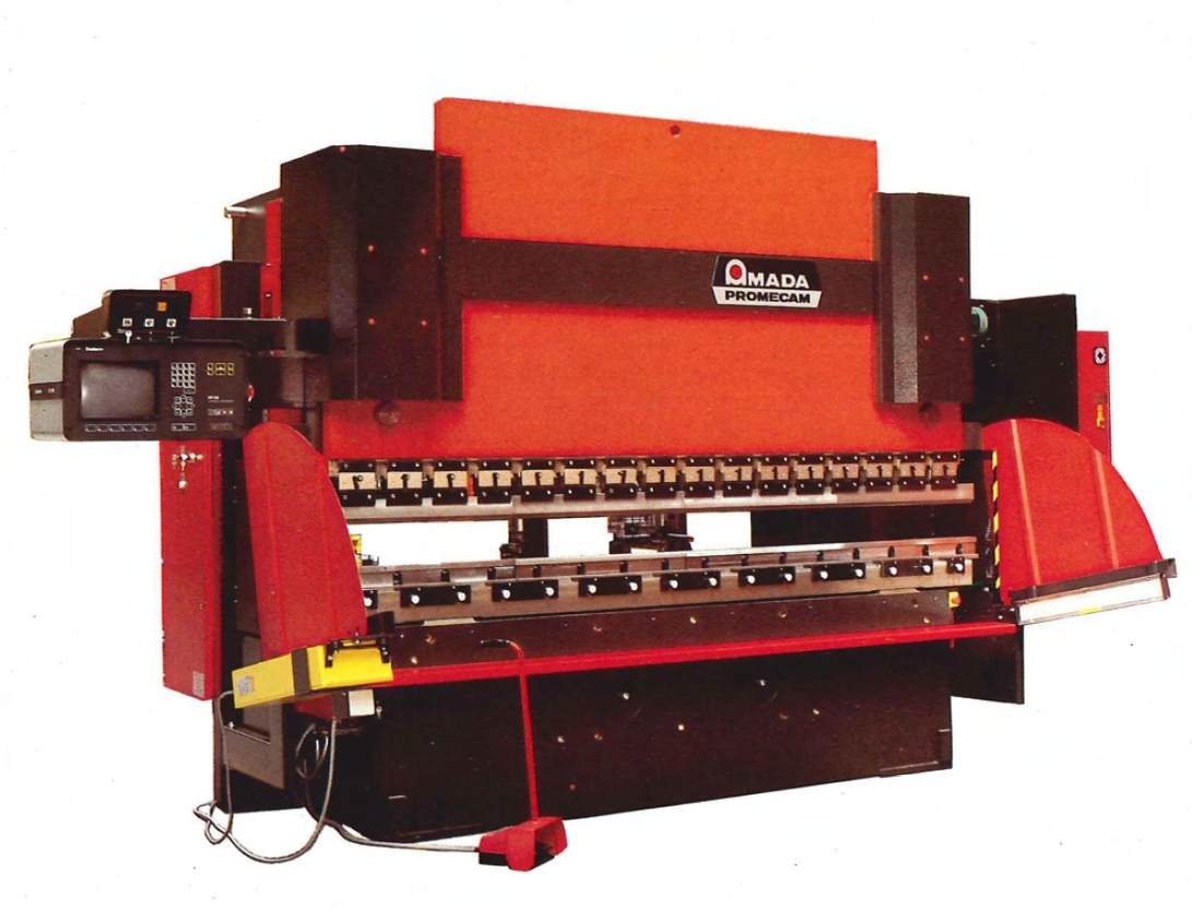
HFB press brake, the ultimate in precision
The HFB press brakes are available in 3 tonnages, 125 t, 170 t and 220 t with 2 bed lengths, 3 and 4 meters. The composite lower bed insures parallel deflection regardless of the bending tonnage. The large distance between side frames, the large throat depth, and the sectionalized punch holder make the HFB press brake a truly versatile machine. In response to the most demanding bending problems, Amada Promecam has developed the HF 700 backgauge with up to 8 independently programmable axes. (Y1 , Y2, X1 , X2, R1, R2, Z1, Z2).
The Operateur, a total control
The Operateur is a CNC control that was totally developed by Amada - Promecam. lt controls all aspects of the HFB press brake yet it is simple to use and it is aesthetically and ergonomically designed. This control includes an integrated maintenance program that can be accessed from the PC through a DNC cable. Amada - Promecam has developed new bending software that provides the ultimate in performance and efficiency.
Ensuring bending quality
Bending accuracy is essentially related to angular precision of the workpiece, which must remain constant throughout the entire length of the bend. A minor variation of punch penetration into the die will lead into considerable variation of the bend angle, even on heavy duty press brakes.
Perfect control of straightness, parallelism and rigidity of the beams is therefore imperative.
"Shimming" a costly solution
To overcome deflection, operators often use out-of-date techniques; most generally inserting shims of various thicknesses above punches or under dies. However the accuracy obtained by this trial-and-error process is time consuming and inevitably leads to increased manufacturing costs.
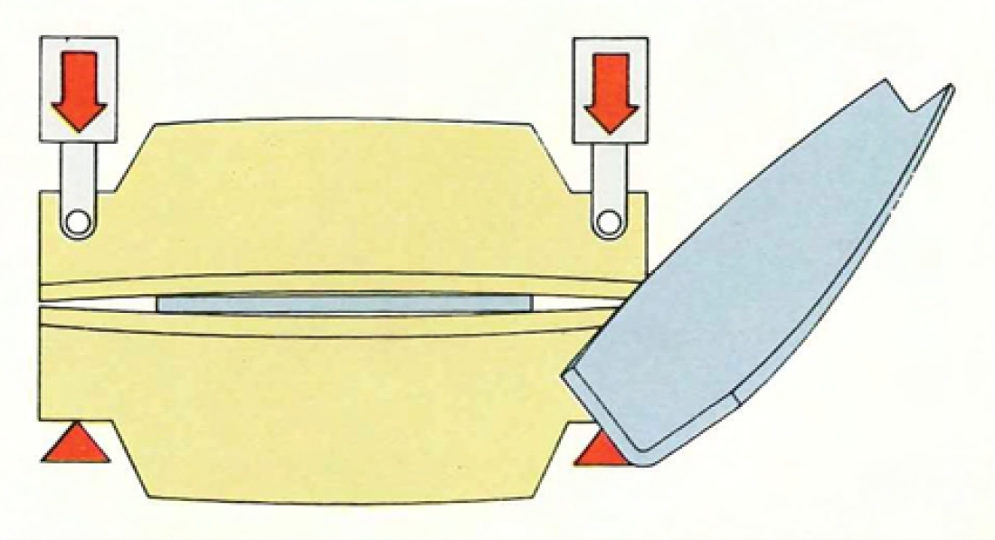
Even the largest press brakes deflect
Conventional press brakes have the lower beam built as a single piece, and the upper beam is driven by two cylinders. Under bending load the two beams deflect in opposite directions accumulating the error and generating a bending angle that varies throughout the bend. To minimize the deflection, frames and beams are commonly oversized up to the limits of manufacturing cost and overall dimensions. Amada - Promecam has developed a new lower beam of unique design that wi ll deflect in the same direction as the upper beam, eliminating the error and generating a constant bending angle throughout the bend.
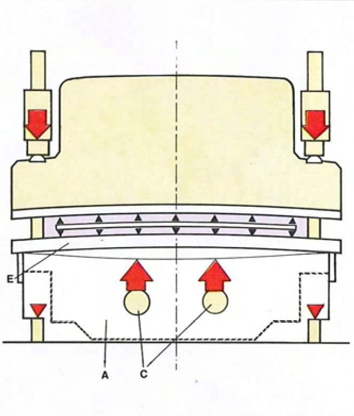
A new concept, the HFB series
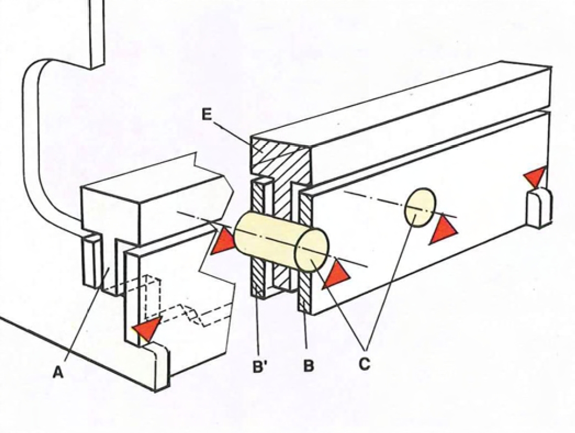
By developing a unique lower fixed beam to work with the conventional moving upper beam, opposing beam deflection is canceled out. The bottom beam is composed of a center plate "A", supporting the work table "E". This centre plate is mounted between two fixed side plates "B" and "B". "A" is supported by two large steel shafts "C" located each side of the brake axis. "B" and "B' "are welded to the side frames. During bending, the reactive forces deform the plate in parallel with the upper beam. Consequently, the deflection of the two beams, is of the same value, thereby ensuring that the punch penetration into the die remains constant throughout its entire length, ensuring accurate bending. This simple, efficient and low cost technique of ensuring constant parallelism between the two beams eliminates the inherent inaccuracy found in conventional press brake designs. All conventional down stroking press brakes utilizing mechanical or hydraulic methods of controlling defl ection are now rendered obsolete by the Amada - Promecam composite lower table patented in 20 countries.
Incremental measurement through accurate sensing
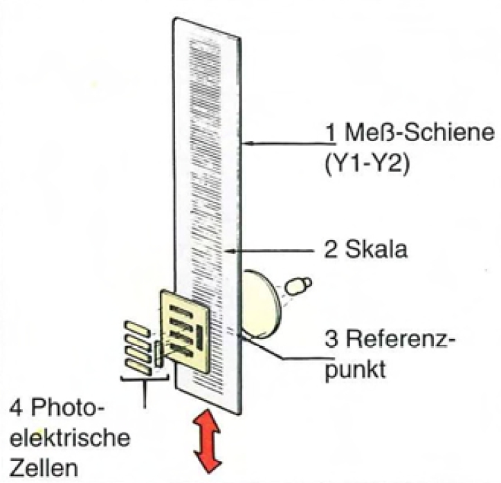
The graduated glass scale regulates the upper beam motion to a positioning accuracy of ± 0.0004" between punch and die.
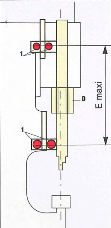
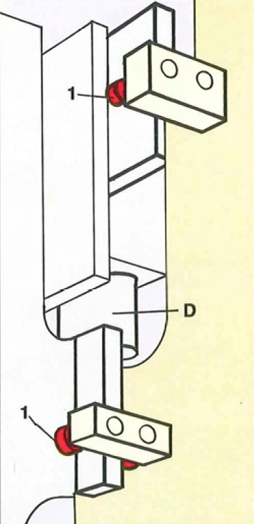
Roller bearing beam guidance
The upper beam is guided by 4 pairs of roller bearing guide assemblies, oversized for added stability. These roller bearings work on hardened and ground surfaces located on the side frame of the machine. The long distance between upper and lower roller bearings (E) as well as zero operating clearances ensures accurate punch and die alignment through the entire stroke length.
Guaranteeing angular accuracy
During normal operation of a press brake, many factors can affect the angular precision of a formed component, including:
- oil viscosity variation through temperature change
- working forces (pressure)
- position of the sheet in relation to the side frames
Without mastering all of these parameters, the quality of bend suffers. A new technique has enabled Amada - Promecam to completely overcome these problems.
Reliable proportional valve system

The sophisticated technique of electronic regulation guarantees parallelism regardless of external elements which might affect it. Incremental linear encoders (Y1 - Y2) are fitted on each end of the upper beam. The sensors are supported by two "C" frames mounted to the lower beam. These optical sensors are electronically connected to the CNC control of the machine (A) which regulates oil flow to each cylinder through proportional valves (B and B'). During the descent of the upper beam, the optical sensors continuously monitor its position with a high degree of precision. The information is transmitted directly to the CNC control which monitors the respective valves. Any informational difference between the two optical sensors automatically commands oil compensation and pressure equalization. The side frame deflection due to the bending force is similarly checked and compensated for.
Large open area at the rear of the machine
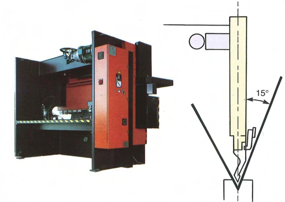
The alignment of the cylinders with the side frames increase the working area at the rear of the upper beam. This arrangement increases the working area available for the operator for complex bends where torsion bars, would prevent the fabrication of some sections, such as large square tanks, boxes, etc ...
Large distance between side frames
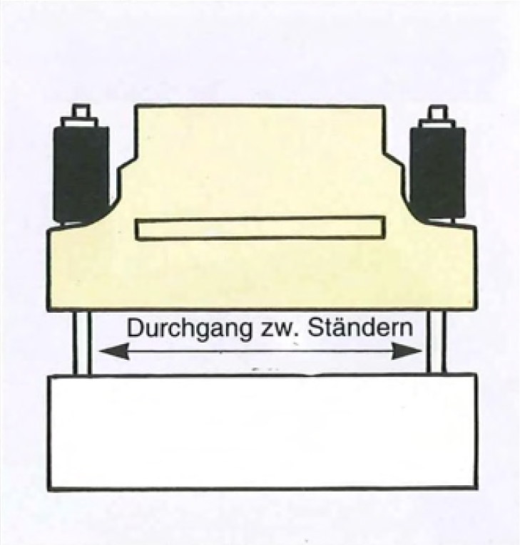
The large distance between side frames allows clearance for wide work pieces.
Throat depth
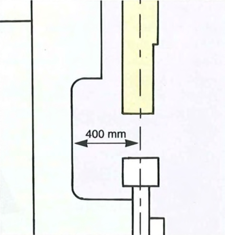
The large throat depth allows for bending up to 410 mm (16") flanges over the entire bed length.
Hand-wheel
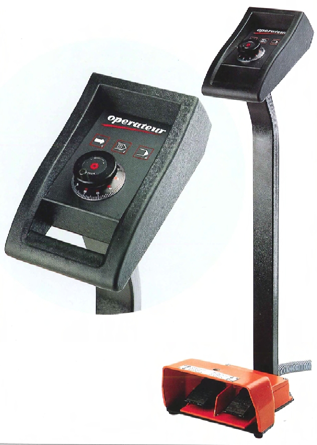
This device allows the operator to regulate the tonnage applied to a workpiece while bending, or to set the angle for the first bend. The wheel is finely graduated to control the progressive variation of penetration between the punch and die.
The Operateur, a total control
By offering our customers a micro-processor, CNC control that is intended for sheet metal machinery, Amada remains on the cutting edge of technology. This new line of CNC controls attains a unique degree of utilization simplicity. Once again Amada provides a complete forming system; machine, CNC control and tooling in a very modern looking and ergonomical package.
The results: a very user friendly bending system that minimizes set-up time and increases overall accuracy.
Depth mode
The operator holds the workpiece against the back gauge finger, and pushes the foot pedal to lower the upper beam to a preset depth. Then, the operator turns the hand wheel that is mounted on the foot pedal. The hand wheel will control the punch penetration into the die. When the desired angle is achieved, the operator presses a button to memorize the ram position.
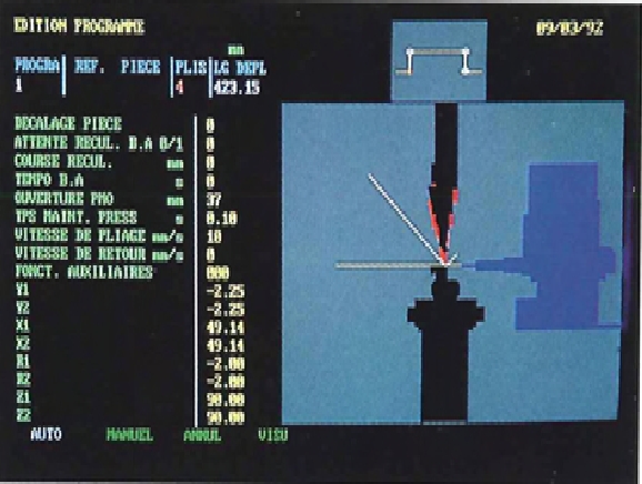
Angle mode
calculates automatically the penetration between the punch and die, the bending speed, and the backgauge finger positions. All other machine functions are entered by the operator.
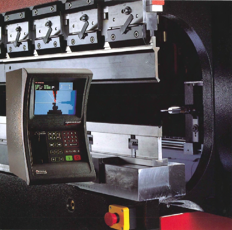
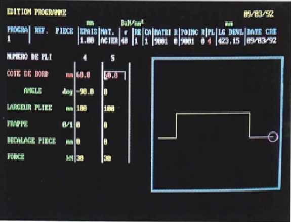
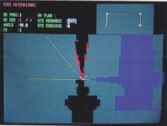
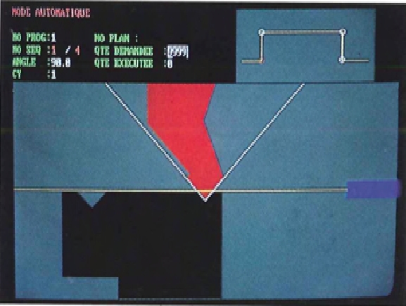
Graphic angle mode
Allows the user to program a part and see its shape on the color CAT. The control will draw the part proportionally to its dimensions. Also the screen will give additio· nal information about the part, such as bending sequence, part rotation, and bending angle. In addition many machine functions normally requiring operator input are automatically calcu· lated and entered into the program.
 |
|
 |
|
 |
|
 |
|
 |
|
 |
|
The high performance backgauge rail
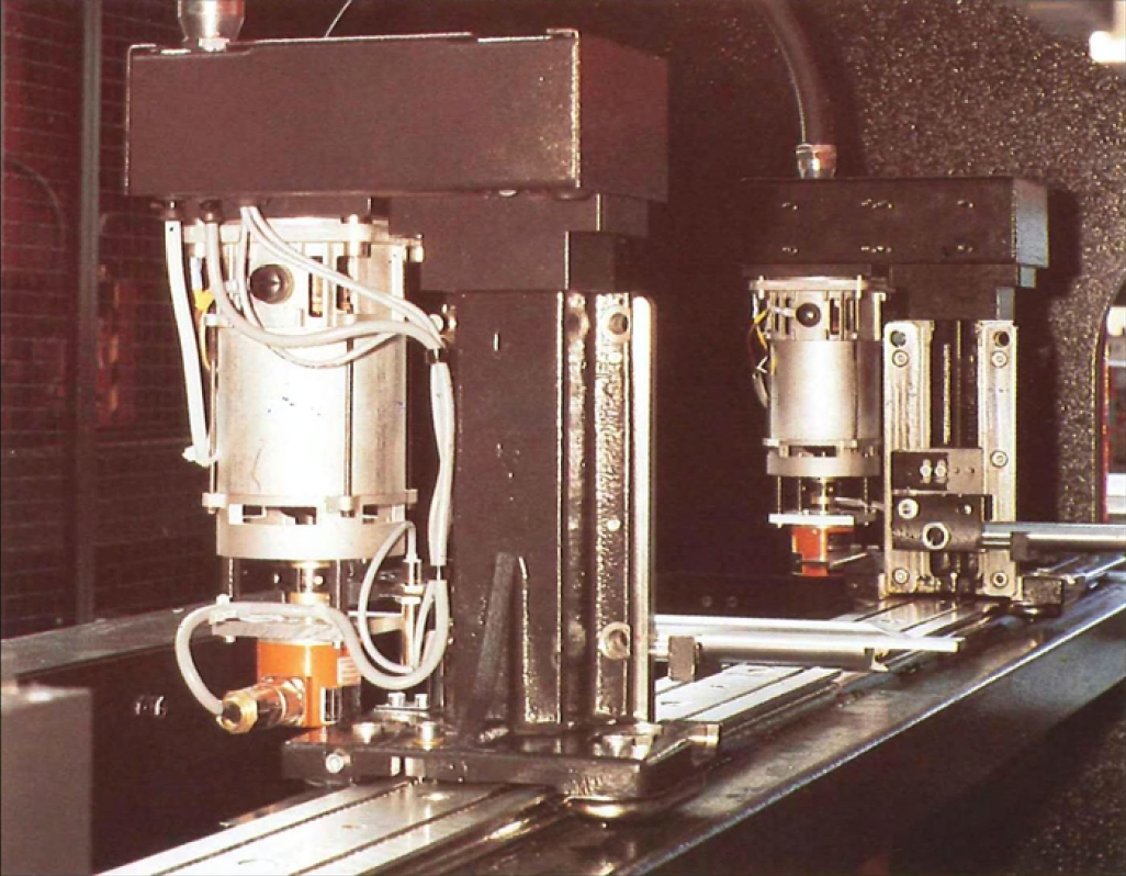
The high performance backgauge rail is made of an extruded aluminum alloy and has been exclusively designed for Amada. The use of this technology allows a very light but strong and rigid moving element, giving maximum speed and maintaining long term accuracy.
Maximum distance between the backgauge drive arms
The backgauge mechanism with independent drive arms mounted directly to the side frames allows maximum opening at the rear of the machine.
Our latest products

EG Series
Servoelectric press brake.
Fast & Accurate, Ergonomic & Compact
Fast & Accurate, Ergonomic & Compact

HFE3i-5012
Ergonomic press brake for small parts bending with AMNC3i controller

HFE-5012 M2 EVO
Ergonomic press brake for small parts bending with AB Pad controller

HFE 3i
Hydraulic press brake with Multi-touch LCD control

HFE M2 EVO
Hydraulic press brake with 12" AB PAD controller

HG
Servo-hydraulic press brake with hydraulic crowning system

HG ATC
Servo-hydraulic press brake with hydraulic crowning system and automatic tool changer

HFE T2
Universal press brake
This product is not longer available
Our current products

ABS-R
6 + 1 axes-bendingrobot for HFP & HFE M2 press brakes with 50 kg payload
EG Series
Servoelectric press brake.
Fast & Accurate, Ergonomic & Compact
Fast & Accurate, Ergonomic & Compact

EG-AR
An all-rounder in the world of bending thanks to automatic robotic systems
HFE 3i
Hydraulic press brake with Multi-touch LCD control
HFE M2 EVO
Hydraulic press brake with 12" AB PAD controller
HFE T2
Universal press brake
HG
Servo-hydraulic press brake with hydraulic crowning system

HG-ARs
6 + 1 axes-bendingrobot system with 20 kg payload and 3000 mm bending length
HG ATC
Servo-hydraulic press brake with hydraulic crowning system and automatic tool changer

HG Rm
6 + 1 axes-bendingrobot system with 80 kg payload and 3000 mm bending length